Introduction
Transcranial magnetic stimulation is performed by passing a current pulse through a coil held near the head (1, 2). The current produces a magnetic field that is changing with time, which causes an electric field in the brain by Faraday induction. The technique is used to study brain function, to diagnose diseases of the central nervous system, and as therapy for depression and other disorders. Traditionally transcranial magnetic stimulation is performed using large coils held outside the head, but recently researchers have developed smaller microcoils that can be implanted in the body to provide a localized stimulus. In this review, microcoil magnetic stimulation is examined from a skeptical point of view. The primary question is: Does a microcoil induce a large enough electric field to activate a neuron? We answer this question by using a simple mathematical model, which reveals that in many cases the electric field is too small—often far too small—to be responsible for nerve excitation.
Transcranial magnetic stimulation
Barker et al. (3) invented the first device widely used for transcranial magnetic stimulation. A typical magnetic stimulation coil has about 10 turns and a diameter of about 10 cm. A current pulse with a rise time of roughly 0.1 ms has an amplitude of approximately 10,000 A. Taking into account the skull and scalp thickness, the coil is about 3 cm from the target neuron. It produces an electric field in the brain of around 80 V/m (Figure 1), which is sufficient to excite the neuron (4).

Figure 1. A contour map of the electric field induced in the brain during transcranial magnetic stimulation. Electric field values are given in volts per meter. The electric field is reduced because of the effect of the scalp and skull boundaries surrounding the brain. Without these boundaries (which we ignore throughout this review), its strength would be approximately 120 V/m. The coil has 8 turns, a diameter of 10 cm, and is held 1 cm above the scalp. The current in the coil rises from zero to 10,000 A in 0.1 ms. The skull and scalp have a combined thickness of 1.8 cm. The electric field is calculated 0.3 cm below the brain surface. Adapted from Roth et al. (4).
In this review, we will need to estimate the electric field during magnetic stimulation. The equation for calculating the electric field, E, is
where μ0/4π is a constant equal to 10–7 (V/m)/(A/s), N is the number of turns in the coil, dI/dt is the time derivative of the current through the coil (or in other words, the rate of change of the current, in A/s), dl is an element along the coil, and R is the distance from the coil element to where the electric field is calculated. The equation consists of two parts: a leading factor μ0/4π N dI/dt that varies with time but not space, and an integral that adds up the contribution from each element of the coil. This integral contains all the spatial information about the electric field but is independent of time. The element of path length dl has units of length, and so does the distance R, so the integral itself is dimensionless. This means the integral, and therefore the electric field, does not change with size (assuming N and dI/dt are the same). If the rate of change of the coil current is held fixed, then the electric field is the same if you calculate it one coil radius below a 10 μm coil or if you calculate it one coil radius below a 10 km coil. Getting close to a nerve (small R) is offset by integrating over a smaller coil.
Let us first calculate the leading, time-dependent factor for a typical magnetic stimulation coil. Consider a coil with 8 turns, where the current rises from zero to 10,000 A in 0.1 ms. Then the leading factor is μ0/4π N dI/dt = (10–7 (V/m)/(A/s)) (8) (10,000 A/0.0001 s) = 80 V/m. Next consider the integral that depends on the coil geometry. Let us assume the electric field is calculated close to the coil, so to a first approximation the coil looks like a long, straight wire of length L. We calculate the electric field at a distance z from the center of this wire. The integral becomes
where dx is an element of the wire lying along the x axis, and is the distance from that element to the point where the electric field is calculated. The limits of the integral extend from −L/2 to +L/2, consistent with the wire having length L. This integral can be looked up in any standard integral table. The result is
where ln is the natural logarithm. You might be tempted to take the limit as L goes to infinity so you can determine the electric field from a long, straight wire, but in that case, the denominator would go to zero and the logarithm would go to infinity. Therefore, we will leave the calculation in terms of the parameter z/L. Note that the integral is indeed dimensionless (the logarithm is a dimensionless function). Also, the logarithm is fairly insensitive to z/L. For instance, if z/L changes from 0.1 to 0.001 (a factor of 100), the integral changes from 4.63 to 13.8 (a factor of 3).
A typical transcranial magnetic stimulation coil has a diameter of 10 cm and is placed about 3 cm from the target neuron, so z/L = 0.3 and the integral becomes 2.6. Therefore, the electric field in the brain induced during magnetic stimulation is about 80 V/m (the time-dependent factor calculated earlier) times the value of the integral (2.6), or 208 V/m. This is somewhat larger than but similar to the peak electric field calculated using a more sophisticated model (Figure 1).
Our model of a wire (or really, a cable with N tightly packed wires) of length L provides only an order-of-magnitude estimate of the electric field. (You should calculate over a closed loop, but we are assuming the other parts of the coil are far enough away that they make a negligible contribution.) Our goal is not to improve upon more sophisticated and detailed electric field calculations, but rather to provide a check on whether these calculations give reasonable results. Such simple “toy” models are useful for assessing the plausibility of results from more complicated but more realistic simulations.
Initial attempts to make microcoils
Transcranial magnetic stimulation has sufficient spatial resolution to cause individual fingers to twitch but has nowhere near enough spatial resolution to excite individual neurons. Ever since the technique was introduced, researchers have attempted to make smaller coils. Cohen and his team sought to make a coil with a diameter of about 1 cm (5, 6). Because this small coil was still placed outside the head, the intervening scalp and skull implied that the distance from the coil to the neuron remained about 3 cm, so z/L = 3, the integral becomes 0.33, and the induced electric field is 26 V/m. This is smaller than for a larger coil like in Figure 1. Moreover, treating the coil as a straight wire of length L is a particularly poor approximation when the electric field is calculated far from the coil (z > L), so the electric field in the brain is likely even smaller still. In order to produce an equivalent electric field in the brain, Cohen and his collaborators had to apply huge currents (tens of thousands of amps) to the small coil, damaging it because of the resulting large magnetic forces and heat. For example, Yunokuchi and Cohen (6) fabricated a single-turn coil a few centimeters in size, but it required so much current that “5/16-in. stainless steel bolts clamping these members together were readily stretched by the repulsive force between the members.”
Bonmassar et al. (7) developed the first true microcoil for magnetic stimulation, intended to be implanted in a patient as part of a prothesis. They wound a small solenoid, 1 mm long and 0.5 mm in diameter with 21 turns, and passed up to 10 A through the coil in 5 μs pulses (Figure 2). They calculated that the electric field 0.3 mm away from the coil was about 6 V/m and showed evidence for the excitation of neurons. They were limited to 10 A because the coil was damaged by greater currents.

Figure 2. Image of a small solenoid, 1 mm long and 0.5 mm in diameter with 21 turns, used for microcoil magnetic stimulation by Bonmassar et al. (7).
We can estimate the electric field induced by Bonmassar et al.’s coil using Eq. 1 with z/L = 0.6 (implying the integral in Eq. 3 equals 1.52).
Given the large difference between a solenoid and a straight wire, the excellent agreement of our estimate with Bonmassar et al.’s calculation is remarkable (and perhaps coincidental). One issue to note is the short pulse duration, which would increase the threshold for excitation because of the neuron’s strength-duration curve (8). If the pulse width were ten times larger (50 μs) using the same peak current, then the rate of change of current and therefore the electric field would be ten times smaller. The threshold electric field, however, would drop by about a factor of ten because of the strength-duration curve. Regardless, our estimate of the electric field strength and Bonmassar et al.’s calculation are nearly the same. The electric field strength approaches the 10 V/m value that corresponds to the threshold stimulus strength (see Section 5).
Bonmassar et al. (7) tested their microcoil by stimulating rabbit retinal ganglion cells in an isolated, perfused retina preparation. Using a patch clamp electrode, they observed action potentials superimposed on their stimulus artifact, occurring about 1 ms after the onset of the stimulus. In a subsequent study, Park et al. (9) used a similar microcoil and observed activation of neural circuits in anesthetized hamsters when they stimulated the dorsal cochlear nucleus and measured from inferior colliculus neurons. Yet another study, by Lee and Fried (10), appeared to use a similar solenoid to suppress activity in the mouse subthalamic nucleus, but the current and number of turns in their coil were not specified, so it is difficult to analyze their experiment.
These results imply that microcoils of about a millimeter in size with many turns and carrying several amperes of current might be used for magnetic stimulation if placed close to the target neuron. Microcoil stimulation in this case is plausible, if technically challenging.
Sub-millimeter sized microcoils
Can microcoils be made even smaller, similar in size to a single neuron (10–100 μm)? The first attempt at such truly tiny coils was made by Lee et al. (11). They initially considered a single-turn “coil” (just a bent wire) L = 1 mm long (Figure 3). Although they would eventually pass currents of 0.05 A through this coil, they performed their calculations using a 3 kHz sinusoidal current with an amplitude of only 0.001 A. They did not specify the distance from the coil to the neuron, but the thickness of the insulation layer was 0.3 μm, so we will use that small distance as z. Thus, z/L = 0.0003, and the approximation of the stimulus as being from a straight wire should be good. They predicted that the electric field is approximately 1 V/m (Figure 3). Let us use Eqs. 1 and 3 to make our own estimate. The peak rate of change (dI/dt) of a sinusoidal current should be 2πIf, where I is the peak current and f is the frequency. For z/L = 0.0003, the integral equals 16.2. Therefore, Eq. 1 gives

Figure 3. The one-turn coil used by Lee et al. is shown on the left in red. It extends in the negative x direction for about 1 mm. The coil carries 0.001 A of current oscillating at a frequency of 3,000 Hz. The target neuron would lie along the x-axis. Their calculated electric field and electric field gradient are shown on the right. Adapted from Lee et al. (11).
The electric field estimated in Eq. 5 using our wire segment approximation is over 10,000 times smaller than that predicted by Lee et at. (11), as shown in Figure 3. There seems to be a fundamental difference between our estimate and their calculation. Moreover, by using such a small value of z (smaller than the diameter of a typical neuron), we probably overestimated the electric field, so the difference is likely even greater. Something is wrong with one of these calculations. Not just a little wrong, as you might expect given the approximations we used, but drastically wrong.
Alzahrani and Roth (12) performed a more accurate calculation of the electric field produced by Lee et al.’s microcoil, using a better approximation for the integral in Eq. 1. They represented the coil as a series of line segments and then integrated over all the segments to get the electric field from the entire coil (13). They found a peak electric field of 0.000021 V/m, close to that estimated above. In addition, a similarly small electric field was calculated by Alzahrani and Roth (12) when analyzing a microcoil used in a subsequent article by the same group (14).
In the experiment of Lee et al. (11), they stimulated the whisker motor cortex of anesthetized mice and used a variety of experimental techniques to detect neural activity, including patch clamp measurements, pharmalogical blockers of synaptic input, and intracellular calcium recording using an optical method. In their experiments, they used currents as large as 0.1 A (as compared to 0.001 A for their numerical simulations) and found a threshold of about 0.05 A, which would increase the induced electric field to 0.0016 V/m. This is still far smaller than the threshold for neural activation.
The threshold for neural stimulation
Most of Lee et al.’s results were expressed in terms of the electric field gradient, dEx/dx (the rate of change of the electric field with distance along the nerve), instead of the electric field, Ex, where the subscript x means the electric field in the direction of the axis of the neuron (Figure 3). Which is appropriate—Ex or dEx/dx—when stimulating the brain?
The hypothesis that dEx/dx is the crucial parameter goes back to a calculation by Roth and Basser (15). They derived the activating function dEx/dx from the cable equation for a nerve axon. This derivation is based on the assumption that you are stimulating a long, straight axon, like found in a peripheral nerve. This model has been tested using in vivo experiments in which the medium nerve in the arm was excited (16) and in an elegant series of in vitro experiments using a pig phrenic nerve isolated in a saline bath (17). In both cases, excitation occurred where dEx/dx was maximum, not where Ex was maximum. These experiments implied that when exciting a long, straight peripheral nerve, dEx/dx is indeed the correct parameter to consider when modeling excitation.
The situation is more complicated in the brain (8). Neurons have axons, but also dendritic trees and cell bodies. These structures often truncate after short distances and curve and bend in various directions. Maccabee et al. (17) showed that a bend in a nerve causes a low-threshold hot spot that excites preferentially. To my knowledge, all these factors have not been sorted out in detail. But given the complexity of the neural geometry in the brain, I suspect neurons will be stimulated where the electric field, rather than the electric field gradient, is maximum.
Suppose, nevertheless, that for the moment we adopt the hypothesis that dEx/dx is responsible for stimulation in the brain. After all, the axon may look long and straight on a spatial scale of 100 μm, even if it bends and terminates over larger distances. What does this imply? Alzahrani and Roth (18) examined the threshold electric field gradient for a long, straight axon when the stimulus was localized. By “localized,” they meant that the electric field varied over distances much smaller than the length constant of the axon. Typical axons have length constants on the order of a millimeter, so Lee et al.’s coil induces an electric field that varies over distances that are short compared to the length constant (Figure 3). What Alzahrani and Roth found was that the threshold value of dEx/dx rose for a localized stimulus (Figure 4). This is analogous to the strength-duration curve: the threshold strength is larger for brief pulses than for longer pulses, at least as long as the pulse duration is shorter than the time constant of the axon. For microcoil stimulation, the threshold strength is larger for localized stimuli than for more diffuse stimuli as long as the distance over which the stimulus changes is shorter than the length constant of the axon. This means you cannot use a threshold value of dEx/dx obtained in a traditional (large coil) magnetic stimulation experiment to determine the threshold value of dEx/dx for a microcoil magnetic stimulation experiment. The two can differ dramatically.

Figure 4. The threshold stimulus strength, dEx/dx, versus the typical distance over which the electric field varies, b. When the electric field varies over a distance of 100 μm (b = 0.01 cm), the threshold rises by over a factor of 100 compared to the threshold for large b. The calculation was performed using a long, straight axon and the Hodgkin-Huxley model for the membrane. A value of 2,000 mV/cm2 corresponds to a value of 20,000 V/m2. From Alzahrani and Roth (18).
For instance, Lee et al. (11) used a value of 11,000 V/m2 for their assumed threshold value of dEx/dx (Figure 3), citing Maccabee et al. (17) as the source of this number. However, Maccabee used a coil that was several centimeters in size, whereas the coil used by Lee et al. was much smaller. According to Alzahrani and Roth (18), the threshold value of dEx/dx appropriate for Lee et al. might be a factor of 100 or more higher than the value found by Maccabee et al., implying the appropriate threshold value for Lee et al. to use might be on the order of 1,000,000 V/m2.
Our discussion so far implies two conclusions: (1) the threshold value of dEx/dx is higher during microcoil stimulation than during traditional stimulation, and (2) dEx/dx is probably not even the appropriate quantity governing the stimulation threshold in the brain. Before we move on, we have two more questions to answer: How did Lee et al.’s calculated value of dEx/dx compare to that using an accurate model of the electric field, and if the electric field Ex is the governing parameter for excitation, what is its threshold value?
For the first question, Alzahrani and Roth (12) calculated both the electric field and its gradient for Lee et al.’s coil. They found that their coil should produce an electric field gradient of approximately 5 V/m2, whereas Lee et al. predicted a value of about 50,000 V/m2 (Figure 3). There is more than a factor of 10,000 difference between these two values. Again, one of these calculations must be wrong.
For the second question, the models of Tranchina and Nicholson (19) and Hause (20) and the experiments of Chan and Nicholson (21) all found that an electric field of about 10 V/m corresponds to the threshold for exciting a neuron. There have been a few experiments, such as the one by Francis et al. (22), that found an electric field as low as 0.1 V/m could, under ideal circumstances, affect the rate of firing of a neural network. Their data suggest that a network of neurons can adjust their aggregate behavior in response to weaker electric fields than those needed to excite a single neuron. In this review, we will adopt a threshold value of 10 V/m, but keep in mind that if you simply want to know if a network of neurons will change its intrinsic firing rate in a continuous way, as opposed to an all-or-none threshold for activation of a single neuron, you may want to use a threshold value as low as 0.1 V/m.
Another way of estimating the threshold electric field strength for a neuron (at least a small neuron) is to assume that the membrane is resistive enough so that no current enters the cell. Then the intracellular space is isopotential, and the transmembrane potential difference between the ends of the cell is approximately the length of the cell times the electric field (8). If a short cell is about a millimeter in length, a 10 V/m electric field would produce a maximum transmembrane potential difference between the ends of the cell of about 10 mV (+5 mV at one end, −5 mV at the other), which is nearly the value of the transmembrane potential required to open sodium channels and trigger an action potential. A very short neuron would be more difficult to excite, and the threshold electric field would be larger. For a long neuron, some current would eventually enter the cell, and the transmembrane potential difference would be better approximated by the length constant of the cell times the electric field (52). Because typical length constants are on the order of a millimeter, this suggests that 10 V/m is approximately the threshold electric field also if applied to the end of a long nerve axon.
The electric field we predicted for Lee et al.’s coil, using a coil current of 0.05 A (which they used in their experiments), is nearly two orders of magnitude lower than even the 0.1 V/m threshold. Induced electric fields by such a coil should have a negligible effect on a neuron.
Microcoil stimulation in the last 10 years
Minusa et al. (23) performed microcoil magnetic stimulation using a solenoid similar to Bonmassar et al. (7): 21 turns, 0.6 mm length, 0.45 mm diameter, passing nearly 3 A pulses with a duration of 0.05 ms. They implanted the microcoil in an anesthesized mouse and detected neural activation in the auditory cortex using flavoprotein autofluorescence imaging, which monitors the mitochondrial energy consumption associated with neural activity. They confirmed that the brain signal arose from neurons because they could abolish it using the sodium channel blocker tetrodotoxin.
Instead of calculating the induced electric field, Minusa et al. focused on the magnetic field produced by the solenoid, which they measured to be on the order of 20–30 mT. To understand the limitations of analyzing a coil in terms of its magnetic field, consider a uniform magnetic field, B, in a solenoid of radius a. If the magnetic field is changing at a rate dB/dt, then the magnitude of the electric field just outside the solenoid is
The factor of the radius a on the right-hand-side of Eq. (6) is the problem. You cannot compare solenoids with different sizes simply in terms of the peak magnetic field, B, or its rate of change, dB/dt. For a given magnetic field strength, the electric field will be stronger outside a large solenoid than outside a small one. The moral of the story is: express the ability to stimulate a neuron in terms of the electric field, not the magnetic field.
In a subsequent article, Minusa et al. (24) created a 4 × 4 array of solenoids, each 1 mm apart. They adjusted the current in each coil to produce the desired electric field. Research using microcoil magnetic stimulation arrays is an active field of study (25–28).
The array used by Rizou and Prodromakis (26) is an interesting case. They claim their peak magnetic field is about 10 mT (similar to Minusa et al.), but their coil size (50 μm) is an order of magnitude less than that of Bonmassar et al. (7) or Minusa et al. (23). Bonmassar et al. predicted an electric field of 6 V/m, so you would expect Rizou and Prodromakis would have an electric field about one tenth of this, or 0.6 V/m. They reported, however, a calculated electric field on the order of several thousand volts per meter. It is not clear why.
Park et al. (29, 30) developed a planar coil with a spiral geometry (Figure 5). A typical coil had 75 turns, and an average diameter of about 5 mm (often the inner and outer diameters could range from 2 to 10 mm). They passed about 2 A of current with a pulse rise time of 0.1 ms. The target neurons were placed close to the coil surface, so the distance z was on the order of 30 μm. Using our single wire model (Eq. 1), we estimate the electric field as
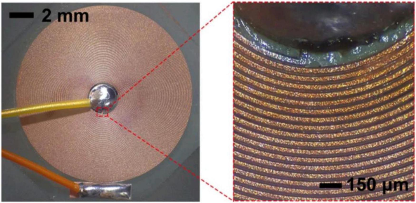
Figure 5. A planar magnetic stimulation microcoil having 75 turns. From Park et al. (30).
Park et al. predicted an electric field somewhat larger than this, but our estimate agrees with theirs within an order of magnitude. This field is below the 10 V/m threshold, but above the lower 0.1 V/m threshold needed to affect a neural network. The microcoil was used to stimulate an isolated hippocampal slice from a mouse. Using recording electrodes to detect the neural activity, Park et al. observed synaptic responses.
Interestingly, Park et al. examined the heating caused by such a coil. The small diameter of their wire increased its resistance, thereby increasing the Joule heating losses. They used a thermocouple to record that their coil could raise the temperature of the surrounding tissue by a few degrees Celsius.
Sugai et al. (31) fabricated small, single-turn coils much like those used by Lee et al. (11). Alzahrani and Roth (12) calculated their electric field and found a value on the order of 0.0001 V/m, which is a hundred times less than can even modulate the firing rate in a neural network. Liu et al. (32) also designed tiny, single-turn coils. They did not report the current passing through the coil, so it is difficult to estimate the electric field that is produced, although it appears to be along the lines of what Lee et al. (11) found.
Khalifa et al. (33) took the design of magnetic stimulation microcoils in yet another direction: using high-magnetic permeability materials inside the coil (Figure 6). One might initially expect that this would increase the electric field by a factor of the relative magnetic permeability, which can be 1,000 or more. However, these coils do not form a closed magnetic circuit. The magnetic field lines must pass out of the high-permeability material and form closed loops in the air or tissue. Khalifa et al. were able to obtain increases in the induced electric field on the order of five to ten compared to similar coils without a high-permeability core. They used calcium fluorescence imaging of neurons in anesthetized mice to confirm neural excitation.

Figure 6. A solenoidal microcoil for magnetic stimulation with an interior (purple) consisting of iron-gallium-boron, which has a relative magnetic permeability of nearly 1,000. From Khalifa et al. (33).
We close this section by examining a series of articles by Saha et al. (34–36). In particular, we focus on Saha et al. (34), where they calculate the electric field 20 μm away from a 5-turn, 200 μm coil carrying a current of 2 A at a frequency of 2,000 Hz. Using our model for a segment of wire (Eq. 1) one last time, we estimate the electric field to be
This is similar to what Saha et al. themselves found for the peak field. This field should be below the threshold for exciting a neuron. When, however, they used the program NEURON to calculate the response of a single 2-mm-long neuron in this field, they found an action potential was excited. It is unclear why this weak of an electric field would be predicted to be above the excitation threshold. Nevertheless, experiments using a cultured human neuroblastoma cell line and calcium fluorescence imaging confirmed neural activation.
If not magnetic stimulation, then what?
In almost every experimental article we have examined—even in the ones for which the induced electric field is estimated to be far too weak for excitation—neurons appear to have been excited. What then is the mechanism by which these coils work? Alzahrani and Roth (37) suggested one possible mechanism: capacitive coupling. The idea is that the coil may be perfectly insulated from the surrounding tissue, in the sense that the coil insulation has a nearly infinite resistance. But the insulation may have capacitance. As current passes through the coil, it may charge or discharge this capacitance, allowing current to enter the tissue (Figure 7). Typically, the current will pass from the wire to the tissue at one end of the coil and then return back from the tissue to the wire at the other end. The current in the tissue might then excite a nearby neuron.

Figure 7. A model for the capacitive coupling of a wire to the surrounding tissue. The wire has a resistance Rcoil, which is enclosed by insulation that has infinite resistance but a capacitance Cinsulation. The surrounding tissue has resistance Rtissue. Current leaves the wire and enters the tissue at the left end of the coil and leaves the tissue and enters the wire at the right end. Adapted from Alzahrani and Roth (37).
When Alzahrani and Roth (37) performed simulations using reasonable values for the coil parameters, they found that the electric field in the tissue caused by magnetic stimulation is about a thousand times smaller than that caused by capacitive coupling. They still found the tissue electric field caused by capacitive coupling is below the 10 V/m threshold to excite neurons, but it was not as far below the threshold as it was for magnetic stimulation.
Their calculation was admittedly an approximation. They represented the tissue as a line of resistors (Rtissue), but the tissue space is actually a three-dimensional volume. They did not have accurate information about the capacitance of the insulation and the resistivity of the tissue. A more sophisticated calculation may better predict the electric field distribution in the tissue. But the model was a start, and it suggested that capacitive coupling might be a more important mechanism than magnetic stimulation.
Capacitive coupling is one alternative mechanism to explain “microcoil magnetic stimulation,” but it is not the only possible mechanism. Some researchers passed several amperes of current through a small coil and observed significant Joule heating. Perhaps a rapid, brief step up in temperature could excite a neuron. Also, current passing through these tiny coils could create magnetic forces acting on one part of the coil by another part, causing motion. This is the reason transcranial magnetic stimulation coils often make “clicking” sounds when they pass current: the coil wires are moving and interacting mechanically, creating the sound. The resulting motion or pressure could trigger excitation. There may be still other mechanisms. However, in my opinion capacitive coupling remains the leading candidate.
Conclusion
Magnetic stimulation by microcoils is an active and growing field in neural stimulation. It may have promise for the development of neural protheses. This review, however, suggests there are many unanswered questions in this area of research:
• What quantity determines if a neuron is excited: the electric field or the electric field gradient?
• Is the threshold electric field gradient for microcoil magnetic stimulation the same as the threshold gradient for transcranial magnetic stimulation?
• What is the magnitude of the electric field induced during microcoil magnetic stimulation?
• What is the mechanism of “microcoil magnetic stimulation”?
Frankly, the field appears prone to errors. One must analyze the articles carefully to separate the wheat from the chaff. Transcranial magnetic stimulation works by magnetic induction. Stimulation using a millimeter-sized, multi-turn coil placed close to the target neuron and carrying several amps of current may work by magnetic induction, but the electric field it generates is sometimes slightly below the threshold value you expect is required to excite neurons. Nevertheless, magnetic induction in these cases seems plausible. On the other hand, when milliamps of current are passed through a single-turn wire, magnetic induction does not seem to be a plausible mechanism for excitation; the electric field appears to be too weak. One alternative mechanism is capacitive coupling. An important goal of future microcoil magnetic stimulation research is to resolve what exactly is the underlying mechanism. The analysis in this review is based on a simple “toy” model of the electric field produced by a microcoil. Differences between this simple model and a more sophisticated and detailed model might arise because the toy model is too simplistic. Nevertheless, the value of a toy model is that it provides an order-of-magnitude estimate of the electric field produced by the coil. If this estimate differs from a more sophisticated model by orders of magnitude, something is significantly wrong with one of the calculations. Another limitation of our analysis is that we assume a single electric field threshold (10 V/m), whereas the actual threshold would depend on details of the neuron morphology and the experimental conditions such as the use of anesthesia. Given the limitations and assumptions, our model is primarily useful for generating a plausibility check on reports in the literature. While such a plausibility check does not provide the final answer as to the ability of microcoils to excite nerves, it does suggest particular cases where more detailed analysis is needed and where mistakes may have occurred.
Author contributions
The author wrote this review article alone and is therefore entirely accountable for its content.
Funding
The author declares that no financial support was received for the research, authorship, and/or publication of this article.
Conflict of interest
The author declares that the research was conducted in the absence of any commercial or financial relationships that could be construed as a potential conflict of interest.
References
2. Roth BJ. The development of transcranial magnetic stimulation. BOHR Int J Neurol Neurosci. (2023) 1:9–21.
3. Barker AT, Jalinous R, Freeston IL. Non-invasive magnetic stimulation of human motor cortex. Lancet. (1985) 1:1106–7.
4. Roth BJ, Saypol JM, Cohen LG, Hallett M. A theoretical calculation of the electric field induced in the cortex during magnetic stimulation. Electroencephalogr Clin Neurophysiol. (1991) 81:47–56.
5. Cohen D, Cuffin BN. Developing a more focal magnetic stimulator. Part I: Some basic principles. J Clin Neurophysiol. (1991) 8:102–11.
6. Yunokuchi K, Cohen D. Developing a more focal magnetic stimulation: part II: fabricating coils and measuring induced current distributions. J Clin Neurophysiol. (1991) 8:112–20.
7. Bonmassar G, Lee SW, Freeman DK, Polasek M, Fried SI, Gale JT. Microscopic magnetic stimulation of neural tissue. Nat Commun. (2012) 3:921.
8. Roth BJ. Mechanisms for electrical stimulation of excitable tissue. Crit Rev Biomed Eng. (1994) 22:253–305.
9. Park HJ, Bonmassar G, Kaltenbach JA, Machado AG, Manzoor NF, Gale JT. Activation of the central nervous system induced by micro-magnetic stimulation. Nat Commun. (2013) 4:2463.
10. Lee SW, Fried SI. Suppression of subthalamic nucleus activity by micromagnetic stimulation. IEEE Trans Neural Syst Rehabil Eng. (2015) 23:116–27.
11. Lee SW, Fallegger F, Casse BDF, Fried SI. Implantable microcoils for intracortical magnetic stimulation. Sci Adv. (2016) 2:e1600889.
12. Alzahrani M, Roth BJ. The electric field induced by a microcoil during magnetic stimulation. IEEE Trans Biomed Eng. (2023) 70:3260–2.
13. Roth BJ, Cohen LG, Hallett M. The electric field induced during magnetic stimulation. Electroencephalogr Clin Neurophysiol. (1991) 43(Suppl):268–78.
14. Lee SW, Thyagarajan K, Fried SI. Micro-coil design influences the spatial extent of responses to intracortical magnetic stimulation. IEEE Trans Biomed Eng. (2019) 66:1680–94.
15. Roth BJ, Basser PJ. A model of the stimulation of a nerve fiber by electromagnetic induction. IEEE Trans Biomed Eng. (1990) 37:588–97.
16. Nilsson J, Panizza M, Roth BJ, Basser PJ, Cohen LG, Caruso G , et al. Determining the site of stimulation during magnetic stimulation of a peripheral nerve. Electroencephalogr Clin Neurophysiol. (1992) 85: 253–64.
17. Maccabee PJ, Amassian VE, Eberle LP, Cracco RQ. Magnetic coil stimulation of straight and bent amphibian and mammalian peripheral nerve in vitro: locus of excitation. J Physiol. (1993) 460:201–19.
18. Alzahrani M, Roth BJ. The difference between traditional magnetic stimulation and microcoil stimulation: threshold and the electric field gradient. Appl Sci. (2024) 14:8349.
19. Tranchina D, Nicholson C. A model for the polarization of neurons by extrinsically applied electric fields. Biophys J. (1986) 50:1139–56.
20. Hause L. A mathematical model for transmembrane potentials secondary to extracellular fields. In: Sances A, Larson SJ editors. Electroanaesthesia: Biomedical and Biophysical Studies. New York: Academic Press (1975).
21. Chan CY, Nicholson C. Modulation by applied electric fields of Purkinje and stellate cell activity in the isolated turtle cerebellum. J Physiol. (1986) 371:89–114.
22. Francis JT, Gluckman BJ, Schiff SJ. Sensitivity of neurons to weak electric fields. J Neurosci. (2003) 23:7255–61.
23. Minusa S, Osanai H, Tateno T. Micromagnetic stimulation of the mouse auditory cortex in vivo using an implantable solenoid system. IEEE Trans Biomed Eng. (2018) 65:1301–10.
24. Minusa S, Muramatsu S, Osanai H, Tateno T. A multichannel magnetic stimulation system using submillimeter-sized coils: system development and experimental application to rodent brain in vivo. J Neural Eng. (2019) 16:066014.
25. Dong L, Qi Y, Luan M, Liu Q, Wang M, Tian C , et al. A multi-channel implantable micro-magnetic stimulator for synergistic magnetic neuromodulation. Brain Res. (2025) 1860:149679.
26. Rizou ME, Prodromakis T. Magnetic stimulation in the microscale: the development of a 6 × 6 array of micro-coils for stimulation of excitable cells in vitro. Biomed Phys Eng Express. (2018) 4:025016.
27. Tian L, Song L, Zheng Y, Wang J. A 4 × 4 array multichannel magnetic stimulation system using submillimeter sized planar square spiral coils: the spatial distribution of electromagnetic field. Int J Appl Electromagn Mech. (2022) 68:329–46.
28. Tian L, Zhao T, Dong L, Liu Q, Zheng Y. Passive array micro-magnetic stimulation device based on multi-carrier wireless flexible control for magnetic neuromodulation. J Neural Eng. (2023) 20:056020.
29. Park HJ, Seol JH, Ku J, Kim S. Computational study on the thermal effects of implantable magnetic stimulation based on planar coils. IEEE Trans Biomed Eng. (2016) 63:158–67.
30. Park HJ, Kang H, Jo J, Chung E, Kim S. Planar coil-based contact-mode magnetic stimulation: synaptic responses in hippocampal slices and thermal considerations. Sci Rep. (2018) 8:13423.
31. Sugai S, Higuchi H, Nishikawa J, Satoh K, Murakami S, Tateno T. Numerical analysis of microcoil-induced electric fields and evaluationof in vivo magnetic stimulation of the mouse brain. IEEJ Trans Electr Electron Eng. (2020) 15:1672–80.
32. Liu X, Whalen AJ, Ryu SB, Lee SW, Fried SI, Kim K , et al. MEMS micro-coils for magnetic neurostimulation. Biosens Bioelectron. (2023) 227:115143.
33. Khalifa A, Zaeimbashi M, Zhou TX, Abrishami SM, Sun N, Park S , et al. The development of microfabricated solenoids with magnetic cores for micromagnetic neural stimulation. Microsyst Nanoeng. (2021) 7:91.
34. Saha R, Benally OJ, Faramarzi S, Bloom R, Wu K, Tonini D , et al. Planar microcoil arrays for in vitro cellular-level micromagnetic activation of neurons. J Vac Sci Technol B. (2024) 42:033001.
35. Saha R, Van Helden D, Hopper MS, Low WC, Netoff TI, Osborn J , et al. Impact of anesthesia on micromagnetic stimulation (mMS) of the vagus nerve. Biomed Phys Eng Express. (2024) 10:035028.
36. Saha R, Goyal A, Yuen J, Oh Y, Bloom RP, Benally OJ , et al. Micromagnetic stimulation (mMS) controls dopamine release: an in vivo study using WINCS Harmoni. Biomed Phys Eng Express. (2025) 11:025058.
37. Alzahrani M, Roth BJ. The calculation of maximum electric field intensity in brain tissue stimulated by a current pulse through a microcoil via capacitive coupling. Appl Sci. (2024) 14:2994.
© The Author(s). 2026 Open Access This article is distributed under the terms of the Creative Commons Attribution 4.0 International License (https://creativecommons.org/licenses/by/4.0/), which permits unrestricted use, distribution, and reproduction in any medium, provided you give appropriate credit to the original author(s) and the source, provide a link to the Creative Commons license, and indicate if changes were made.